In 2008, both Varian and Elekta received FDA clearances for their VMAT solutions. Today VMAT is a widely used treatment technique and it is usually preferred for its ability to deliver dose distributions of similar plan quality as IMRT, but with a much shorter delivery time. The linac vendors argue that an expensive hardware upgrade is needed to be able to deliver VMAT. This upgrade includes the ability to vary the dose rate of the beam while moving the gantry and the leaves. Long before 2008 it was possible to deliver conformal arcs, where the leaves moved to maintain the target projection from all angles while the gantry rotated around the patient. These conformal arcs were delivered using constant dose rate and constant gantry speed. If the plan is optimized using inverse planning it is possible to utilize the ability to move the leaves to create modulated arcs, instead of conformal arcs, even though the dose rate and gantry speed are constant.
Method
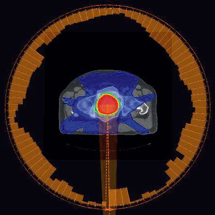
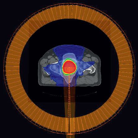
When optimizing variable dose rate VMAT (VDR) beams, the leaf positions and the MU of each control point are optimized simultaneously (Figure 1). Since the MU is not allowed to be individually optimized for each control point for a constant dose rate VMAT (CDR) beam (Figure 2), it is likely that the plan quality is reduced compared to a VDR beam with the same angle settings.
To obtain a good quality dose distribution using CDR, the delivery time is usually increased compared to the VDR beam. The reason is that the gantry is not allowed to move faster from the directions where little dose is desired. Instead the optimizer closes the leaves faster from these directions to create smaller MLC openings.
Figure 1: VDR plan for prostate patient P1. The orange bars around the patient indicates the MU delivered from the different directions. For the VDR plan, the MU per gantry angle varies. The total MU is 491MU and the delivery time is 68 seconds.Figure 2: CDR plan for prostate patient P1. For the CDR plan, the MU per gantry angle is constnant. The total MU is 465 MU (5.19 MU/cp) and the delivery time is 93 seconds.
To increase the plan quality of the CDR plans, it is possible to split the arc in several subarcs (Split-CDR or SCDR). Each subarc can have a different dose rate and gantry speed resulting in different MU per degree for each subarc, which increases the possibilities to obtain a good quality plan in shorter beam on time. Assuming a fast therapist, i.e. negligible time to switch the key, it takes 15 seconds to change beam using a Varian 2100*. Therefore, the number of subarcs, should be kept as low as possible to decrease the total delivery time of the plan. To increase the benefit of splitting the arc, the split angles must be individualized for each patient (Figure 3).
In this study five prostate and three head and neck patients were optimized in RayStation using one upgraded (VDR) and one non-upgraded (CDR) Varian 2100 linac. First, an ideal step-andshoot (SMLC) plan for each patient was manually created using inverse planning. A script was created to automatically generate one VDR plan, one CDR plan and 5 SCDR plans. Dose mimicking was used to recreate the DVHs of the ideal plans as close as possible. To achieve nearly identical target doses for all dose mimic plans, higher weights on the target objectives were used compared to the weights of the healthy tissue objectives. Since 9 beams and 200 segments were used for the ideal plans, it is not possible improve any of the VMAT plans after dose mimicking without compromising some other objective, because they are Pareto optimal.
The split angles of the SCDR plans were determined by minimizing the variance of the control point MU obtained when optimizing the VDR plan. 1, 2, 3, 4 and 9 splits were applied per original beam. The SCDR plan with the lowest number of splits and a dose distribution that were comparable with the dose distribution of the VDR plan was selected as the SCDR plan of that particular patient. A gantry spacing of 4 degrees was used for all VMAT plans resulting in 91 control points for a full arc.
* Measurements done at Putnam Hospital Center, HealthQuest Affiliate, 670 Stoneleigh Avenue, Carmel, NY 10512, USA.
Figure 3: The two subarcs of the selected SCDR plan (1 split) for the prostate patient P1. The first subarc (left) covers gantry angles 181-141 degrees, and the second subarc (right) covers gantry angles 141-179 degrees. The split angle is determined from the VDR plan in Figure 1, and the second subarc corresponds to the low MU part at the end of the VDR beam. The MU per control point in subarc 1 is slightly increased from 5.19 MU/cp to 6.23 MU/cp compared to the CDR beam, whereas the MU/cp of subarc 2 is reduced to 1.82 MU/cp. The delivery times of the subarcs are 60 and 10 seconds, and adding a 15 second penalty of switching beam the total delivery time is 85 seconds which is less than for the CDR plan without split (93 seconds). As can be seen in the DVHs in Figure 3 the dose to rectum is reduced by the split and comparable to the rectum dose of the VDR plan. The total MU of the two subarcs is 516 MU.
RESULTS AND DISCUSSION
Prostate
Table 1 shows the delivery times for the five prostate patients, including the 15 seconds penalty to change beam. The VDR and CDR plans are full single arcs from 181 to 179 degrees gantry angle. In the SCDR case the original arc is split 1 to 4 times, i.e. into 2 to 5 subarcs. The mean number of splits is 2.2. The mean delivery times of the VDR and the SCDR plans are both below 2 minutes. It is also interesting to note that the mean delivery times of CDR and SCDR are comparable even though the SCDR plans has a 15 seconds penalty for each split. This is because the gantry speed is allowed to change between the subarcs. The CDR technique without split usually gives a descent plan, but SCDR achieves plan quality comparable to the corresponding VDR plan (Figure 4).
Patient
VDR Delivery time (sec)
CDR Delivery time (sec)
SCDR Delivery time (sec)
SCDR #Splits per arc
P1
68
93
86
1
P2
65
126
123
2
P3
66
120
97
1
P4
65
126
139
3
P5
71
114
147
4
Mean
67
116
118
2.2
Table 1:The delivery times for the VDR, CDR and selected SCDR plans are shown for the five prostate patients, together with the mean delivery time of each treatment technique. The number of splits for the selected SCDR plans are also shown. For each split a 15 seconds penalty to change the beam has been added to the total delivery time of the SCDR plans.
Figure 4: The DVHs of patient P1 are shown to illustrate the improvement in plan quality when applying SCDR on a prostate case. Note that both rectum (brown) and bladder (yellow) protection are improved by splitting the CDR beam (dashed) into SCDR beams (dotted), and comparable to the VDR plan (solid). The target (red) and the external (dark green) DVHs are nearly identical when comparing the different treatment techniques. Similar results were obtained for all five prostate patients.
Head and neck
Table 2 shows the delivery times for the three head and neck patients, including the 15 seconds penalty to change beam. In this case the VDR and CDR plans consist of two arcs in opposite directions. The collimator is tilted 45 degrees for one of the arcs and -45 degrees for the other arc. In the SCDR case each original arc is split into the same number of subarcs. Using SCDR it was possible to create head and neck plans with comparable plan quality as the corresponding VDR plans (Figure 5). The number of splits per original arc ranged from 0 to 3 resulting in 2 to 8 subarcs. The mean number of splits was 1.3 per original arc. The mean delivery time for VDR and SCDR are both in the interval 2 to 4 minutes. The longer delivery times for SCDR is mainly due to the 15 seconds penalty of switching beam.
Patient
VDR Delivery time (sec)
CDR Delivery time (sec)
SCDR Delivery time (sec)
SCDR #Splits per arc
HN1
145
166
166
0
HN2
145
198
287
3
HN3
145
240
255
1
Mean
145
201
236
1.3
Table 2:The delivery times for the VDR, CDR and selected SCDR plans are shown for the three head and neck patients, together with the mean delivery time of each treatment technique. The number of splits per arc for the selected SCDR plans are also shown. Since these plans consist of two original arcs, 2\*15 seconds are added for each split, plus 15 seconds to change beam when the arc direction is changed. Since the VDR and CDR plans consist of two full arcs a 15 seconds penalty for changing beam is added to these plans as well.
Figure 5: The DVHs of patient HN3 are shown to illustrate the improvement in plan quality when applying SCDR on a head and neck case. Note that both spinal cord (light green) and parotid (dark blue and dark purple) protection are improved by splitting the CDR beams (dashed) into SCDR beams (dotted), and comparable to the VDR plans (solid). The target (cyan and orange) and the external (dark green) DVHs are nearly identical when comparing the different treatment techniques. Similar results were obtained for patient HN2. Patient HN1 did not need any split to match the VDR plan, probably because the two original arcs already allowed two dose rates.
CONCLUSION
Using modern and innovative treatment planning tools, it is possible to create deliverable SCDR plans with comparable plan quality as corresponding VDR plans, without upgrading the linac to variable dose rate. The delivery times of both the VDR and the SCDR plans are significantly shorter than what is reported for IMRT plans. The mean delivery times of the tested prostate plans are between 1 and 2 minutes for both techniques, and between 2 and 4 minutes for the tested head and neck plans.